

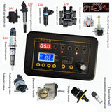

Automobile Actuator Fault Detector Car Coil Ignition Idle Stepping Motor Solenoid Valve Injector Tester
This Automobile Actuator Fault Detector can not only drive and test various actuators, but also simulate duty cycle sensors to detect whether the actuator is faulty or the circuit or ECU computer is faulty.
In addition, it also has reverse connection protection and overcurrent protection, and it will automatically cut off when the current is too large.

Automobile Actuator Fault Detector Main Functions:
1. Drive test ignition coil: 12V gasoline vehicle ignition coil: 12V-24V natural gas ignition coil.
2. Drive test fuel injector: 12V gasoline vehicle fuel injector, 12V-24V diesel fuel injector.
3. Drive and test solenoid valves controlled by various duty ratios, such as fuel metering valves, EGR valves, etc.
4. Drive test various duty cycle control motors. For example: electronic throttle motor, urea pump motor, etc.
5. Drive test idling stepper motor, instrument stepper motor, headlight range stepper motor, etc.
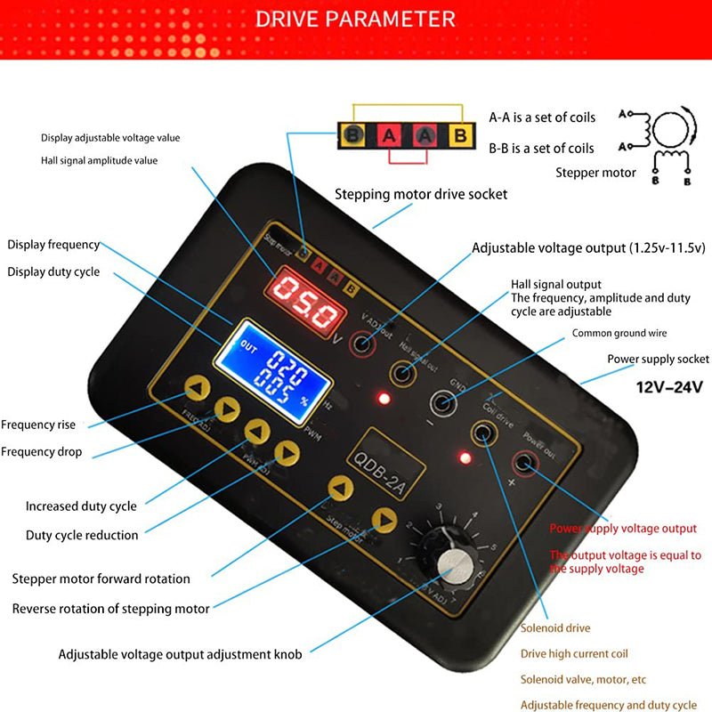
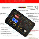
6. Output frequency, amplitude, duty cycle adjustable Hall signal, electronic module for driving duty cycle control, and can also simulate duty cycle sensors such as: air conditioner pressure sensor (duty cycle type), Air flow meter (duty cycle type), etc.
7. Power supply voltage: 12V-24V, with reverse polarity protection, over-current protection and automatic power-off if the current is too large.

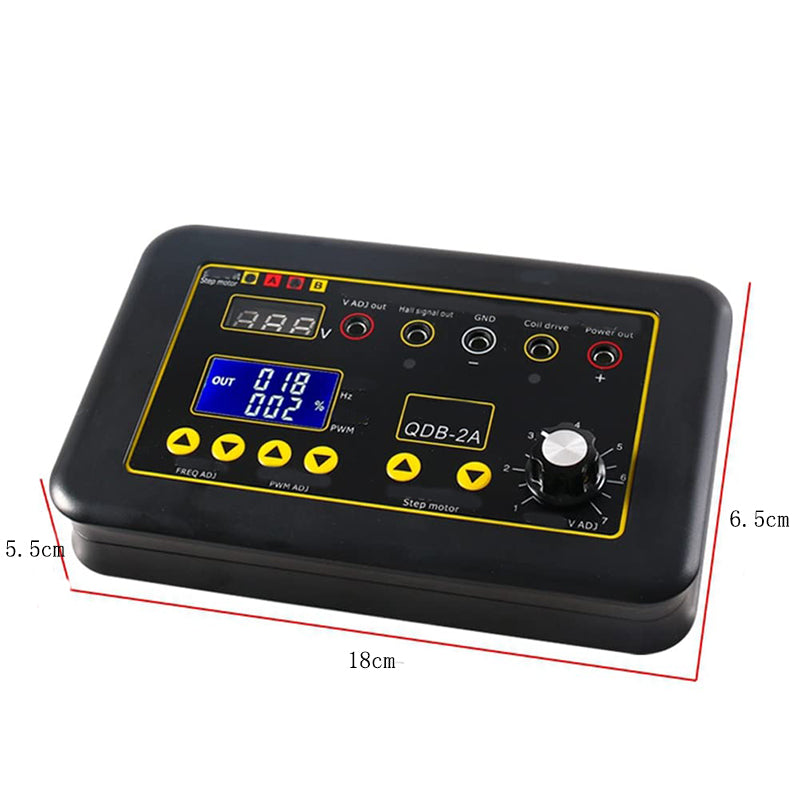
Automobile Actuator Fault Detector's Parameter:

Automobile Actuator Fault Detector's Instructions for use:
Ignition coil test:
Internal drive module with power
Urea pump motor module
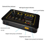
The above coils and motors are equipped with power amplification modules, so only need to input the Hall signal to drive the test. The drive module generally has three lines, namely: power supply +, ground -, signal input test steps.
1. Power the driver, choose 12V or 24V according to the voltage of the module under test
2. If the ignition coil (with power module inside) is tested, the frequency is adjusted to 10-40HZ, the duty cycle range is 95%-99% (the Hall signal socket outputs a negative duty cycle signal), and the adjustable voltage is adjusted to 5-11V
If the motor module is tested, the frequency is adjusted to 50HZ-200HZ, the duty cycle range is 1%-99%, and the adjustable voltage is adjusted to 5-11V.
3. Connect the power supply + terminal of the module under test to the power supply voltage output socket, connect the module ground - terminal to the ground wire socket, and connect the signal input to the Hall signal output socket. At this time, the module under test should be able to work normally.

High Current Solenoid Coil Test Instructions:
Ignition coil (without power module inside), fuel injector, solenoid valve, electronic throttle motor, etc. The internal principle of the above actuators is an electromagnetic coil with two terminals Test method.
1. Plug the driver into the external power supply.
2. Adjust frequency and duty cycle:
If testing the ignition coil and fuel injector, adjust the frequency to 10-40HZ, and the duty cycle range is 1%-5%. If testing the solenoid valve, throttle motor, adjust the frequency to 50-200HZ, and the duty cycle range is 1%-90%.
Stepper motor drive test:
Stepping motors for automobiles mainly include: instrument stepping motors, total speed stepping motors, headlight follow-up steering and headlight height adjustment stepping motors, etc. Stepping motors are composed of two sets of coils, namely, group A coils and group B coils Test stepper motor steps.
1. Plug the driver into the external power supply (the voltage should not exceed 12V).
2. Use a multimeter to measure the two sets of coils of the stepping motor, then connect the AA and BB of the driver respectively, press the button of the stepping motor, the stepping motor should rotate normally, if not, the stepping motor is faulty

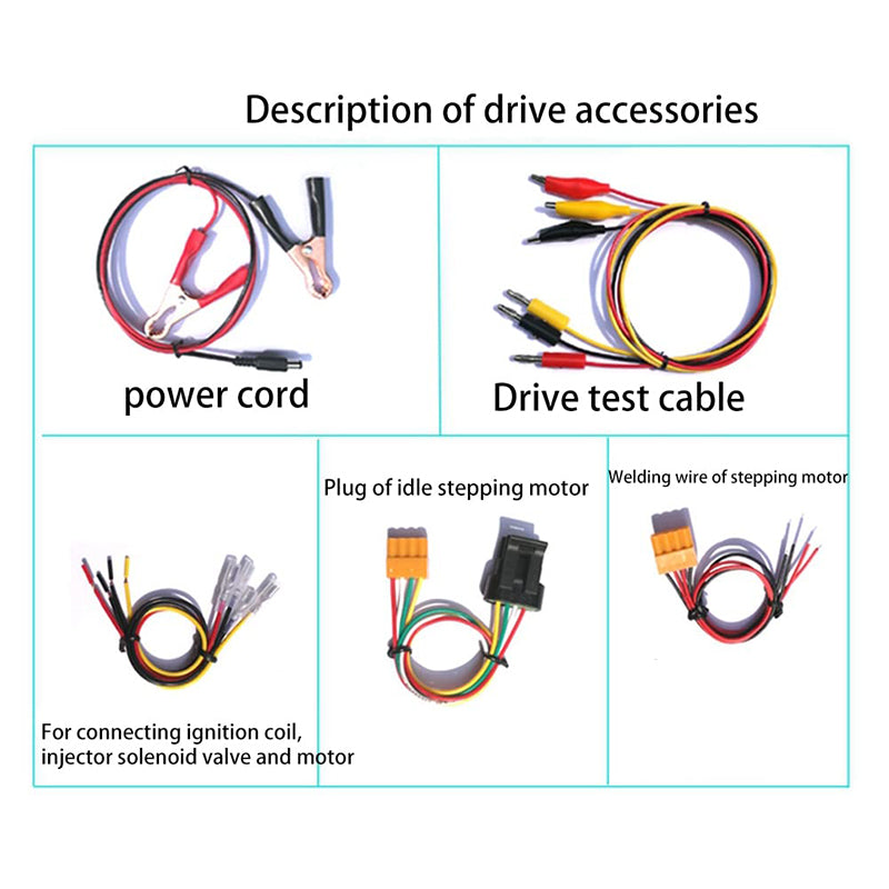
Automobile Actuator Fault Detector's Packing List:
1pc* Automobile Actuator Fault Detector
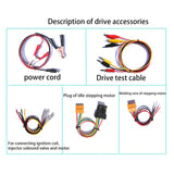
3pcs* drive test cable (red 1, yellow 1, black 1)
1pc*power cord
4pcs*4 single plugs (red 1, yellow 1, black 2) to connect the ignition coil, fuel injector solenoid valve, motor
1pc* total speed stepper motor plug (for total speed stepper motor)
1pc* stepper motor welding wire (for instrument stepper motor headlight follow-up steering stepper motor)

Automobile Actuator Fault Detector Car Coil Ignition Idle Stepping Motor Solenoid Valve Injector Tester
This Automobile Actuator Fault Detector can not only drive and test various actuators, but also simulate duty cycle sensors to detect whether the actuator is faulty or the circuit or ECU computer is faulty.
In addition, it also has reverse connection protection and overcurrent protection, and it will automatically cut off when the current is too large.
Automobile Actuator Fault Detector Main Functions:
1. Drive test ignition coil: 12V gasoline vehicle ignition coil: 12V-24V natural gas ignition coil.
2. Drive test fuel injector: 12V gasoline vehicle fuel injector, 12V-24V diesel fuel injector.
3. Drive and test solenoid valves controlled by various duty ratios, such as fuel metering valves, EGR valves, etc.
4. Drive test various duty cycle control motors. For example: electronic throttle motor, urea pump motor, etc.
5. Drive test idling stepper motor, instrument stepper motor, headlight range stepper motor, etc.
6. Output frequency, amplitude, duty cycle adjustable Hall signal, electronic module for driving duty cycle control, and can also simulate duty cycle sensors such as: air conditioner pressure sensor (duty cycle type), Air flow meter (duty cycle type), etc.
7. Power supply voltage: 12V-24V, with reverse polarity protection, over-current protection and automatic power-off if the current is too large.
Automobile Actuator Fault Detector's Parameter:
Automobile Actuator Fault Detector's Instructions for use:
Ignition coil test:
Internal drive module with power
Urea pump motor module
The above coils and motors are equipped with power amplification modules, so only need to input the Hall signal to drive the test. The drive module generally has three lines, namely: power supply +, ground -, signal input test steps.
1. Power the driver, choose 12V or 24V according to the voltage of the module under test
2. If the ignition coil (with power module inside) is tested, the frequency is adjusted to 10-40HZ, the duty cycle range is 95%-99% (the Hall signal socket outputs a negative duty cycle signal), and the adjustable voltage is adjusted to 5-11V
If the motor module is tested, the frequency is adjusted to 50HZ-200HZ, the duty cycle range is 1%-99%, and the adjustable voltage is adjusted to 5-11V.
3. Connect the power supply + terminal of the module under test to the power supply voltage output socket, connect the module ground - terminal to the ground wire socket, and connect the signal input to the Hall signal output socket. At this time, the module under test should be able to work normally.
High Current Solenoid Coil Test Instructions:
Ignition coil (without power module inside), fuel injector, solenoid valve, electronic throttle motor, etc. The internal principle of the above actuators is an electromagnetic coil with two terminals Test method.
1. Plug the driver into the external power supply.
2. Adjust frequency and duty cycle:
If testing the ignition coil and fuel injector, adjust the frequency to 10-40HZ, and the duty cycle range is 1%-5%. If testing the solenoid valve, throttle motor, adjust the frequency to 50-200HZ, and the duty cycle range is 1%-90%.
Stepper motor drive test:
Stepping motors for automobiles mainly include: instrument stepping motors, total speed stepping motors, headlight follow-up steering and headlight height adjustment stepping motors, etc. Stepping motors are composed of two sets of coils, namely, group A coils and group B coils Test stepper motor steps.
1. Plug the driver into the external power supply (the voltage should not exceed 12V).
2. Use a multimeter to measure the two sets of coils of the stepping motor, then connect the AA and BB of the driver respectively, press the button of the stepping motor, the stepping motor should rotate normally, if not, the stepping motor is faulty
Automobile Actuator Fault Detector's Packing List:
1pc* Automobile Actuator Fault Detector
3pcs* drive test cable (red 1, yellow 1, black 1)
1pc*power cord
4pcs*4 single plugs (red 1, yellow 1, black 2) to connect the ignition coil, fuel injector solenoid valve, motor
1pc* total speed stepper motor plug (for total speed stepper motor)
1pc* stepper motor welding wire (for instrument stepper motor headlight follow-up steering stepper motor)